Consider the circuit:
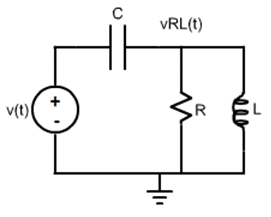
The circuit will be studied for two output variables: (1) the voltage in the capacitor,
v_{C}(t); and (2) the voltage in the Rl connection,
v_{RC}(t).
The transfer functions for the two output variables are:
H_{C }(s)=\frac{\frac{1}{RC}\: s+\frac{1}{LC}}{s^{2}+\frac{1}{RC}s+\frac{1}{LC}}
H_{RL}(s)=\frac{s^{2}}{s^{2}+\frac{1}{RC}s+\frac{1}{LC}}
The Laplace Transforms of the output variables when a generic input
v(t), whose Laplace Transform is
V(s), is applied are:
V_{C}(s)=H_{C}(s)\: V(s)=\frac{\frac{1}{RC}\: s + \frac{1}{LC}}{s^{2} + \frac{1}{RC}s + \frac{1}{LC}}\: V(s)
V_{RL}\left ( s \right )=H_{RL}(s)\: V\left ( s \right ) = \frac{s^{2}}{s^{2} + \frac{1}{RC}s + \frac{1}{LC}}\: V\left ( s \right )
The time domain expressions of both voltages can be found applying the Inverse Laplace Transform, as follows:
v_{C}(t)=\mathfrak{L}^{-1}\left [ V_{C}(s) \right ]=\mathfrak{L}^{-1}\left [ \frac{\frac{1}{RC}\: s + \frac{1}{LC}}{s^{2} + \frac{1}{RC}s + \frac{1}{LC}}\: V(s) \right ]
v_{RL}(t)=\mathfrak{L}^{-1}\left [ V_{RL}(s) \right ]=\mathfrak{L}^{-1}\left [ \frac{ s^{2}}{s^{2} + \frac{1}{RC}s + \frac{1}{LC}}\: V(s) \right ]
Compute the responses to the chosen input functions. Define the parameters and write them in the “boxes”.
•Responses in the Time Domais
Impulse Response of the Voltage in the Capacitor
• Responses in the Frequency Domain - Bode Plot
Bode Plot of the Voltage in the Capacitor