Consider the circuit:
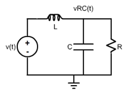
The circuit will be studied for two output variables: (1) the voltage in the inductor,
v_{L}(t); and (2) the voltage in the RC connection,
v_{RC}(t) .
The transfer functions for the two output variables are:
H_{L}(s)=\frac{s^{2}+\frac{1}{RC}s}{s^{2}+\frac{1}{RC}s+\frac{1}{LC}}
H_{RC}(s)=\frac{\frac{1}{LC}}{s^{2}+\frac{1}{RC}s+\frac{1}{LC}} >
The Laplace Transforms of the output variables when a generic input
v(t), whose Laplace Transform is
V(s) , is applied are:
V_{L}(s)=H_{L}(s)\: V(s)=\frac{s^{2}+\frac{1}{RC}s}{s^{2}+\frac{1}{RC}s+\frac{1}{LC}}\: V(s)
V_{RC}(s)=H_{RC}(s)\: V(s)=\frac{\frac{1}{LC}}{s^{2}+\frac{1}{RC}s+\frac{1}{LC}}\: V(s)
The time domain expressions of both voltages can be found applying the Inverse Laplace Transform, as follows:
v_{L}(t)=\mathfrak{L}^{-1}\left [ V_{L}(s) \right ]=\mathfrak{L^{-1}}\left [ \frac{s^{2}+\frac{1}{RC}s}{s^{2}+\frac{1}{RC}s+\frac{1}{LC}}\: V(s) \right ]
v_{RC}(t)=\mathfrak{L}^{-1}\left [ V_{RC}(s) \right ]=\mathfrak{L^{-1}}\left [ \frac{\frac{1}{LC}}{s^{2}+\frac{1}{RC}s+\frac{1}{LC}}\: V(s) \right ]
Compute the responses to the chosen input functions. Define the parameters and write them in the “boxes”.
• Responses in the Time Domain
Impulse Response of the Voltage in the Inductor
• Responses in the Frequency Domain - Bode Plot
The Bode Plot, magnitude and phase graphics, can be determined for different variables, as follows. Choose the values of the parameters and the frequency range and write them in the boxes.
Bode Plot of the Voltage in the Inductor