|
|
RC SERIES CIRCUIT
| THE MATHEMATICAL MODEL OF THE RC SERIES CIRCUIT |
| |
|
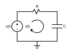
Consider the RC series circuit shown in the figure:
|
|
|
Since it is a series circuit, the source current is the same of the resistor and the capacitor.
|
Using Kirchhoff Voltage Law, the time domain mathematical model can be written. It is the following first order ordinary linear differential equation with constant coefficients:
v(t) = R.i(t) + \frac{1}{C} \int_{0}^{t}i(\tau) d\tau; ~i(0) = 0
In case you want to remember Kirchhoff Voltage Law, click on the magnifying glass.  The equation can be solved for three variables – the current, the voltage in the resistor and the voltage in the capacitor. The current and the voltage in the resistor have the same shape with different amplitude, since their relation is:
v_R(t) = R.i(t)
Thus, it is possible to solve for one of the variables and compute the other either by dividing or by multiplying by R. When filters are studied, the variables are all voltages, for this reason, the equation will be solved for both voltages.
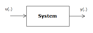
Initially, the object addresses the voltages. The starting point is the impulse response. If you want to remember the concept of the impulse response of a LTIS – Linear Time Invariant System, click on the magnifying glass.
|

|

|
|


 – for continuos time systems
 – for discrete time systems

