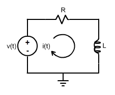
Consider the
RL circuit of the figure below:
This circuit may be used as a first order filter. If the output is the voltage in the inductor, then the circuit is a high-pass (HP) filter. In case the output is the voltage in the resistor, the filter is low-pass (LP).
When the output is in the inductor (HP) the transfer function is:
H(s)_{PA} = \frac{s}{s + \frac{R}{L}}
a) Analyze the Bode Plot of this high-pass filter for different values of
R and/or
L.
When the output is in the resistor (LP) the transfer function is:
H(s)_{PB} = \frac{\frac{R}{L}}{s + \frac{R}{L}}
b) Analyze the Bode Plot of this low-pass filter for different values of
R and/or
L.